Antlion / Components / Axis
AxisAXIS-002
Divides the start line into the planes each stand section is placed on. Straight runs are split by an even module, arcs by a fixed count — so section spacing follows the shape.
1Plan & setup
2Section
32D layout
43D solids
5Analysis
Fig. 1 — PortsReads left, writes right
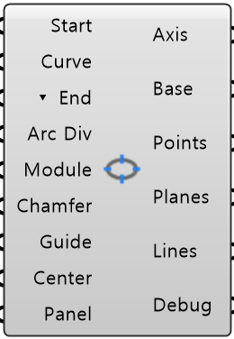
Start Line StartObject · itemThe start line from any Startline component
Start Line Curve CurveCurve · itemDivide this curve instead
End Mode ▾ EndText · itemWhat to do with the leftover at the end of a straight run
Arc Division Arc DivInteger · itemHow many sections each corner arc is divided into
Module Number · itemSection spacing on the straight runs, adjusted to fit each run evenly
Chamfer Module ChamferNumber · itemSpacing along chamfered corner edges
Guide Length GuideNumber · itemLength of the preview line drawn at each axis
Center Axis CenterBoolean · itemAlso put a section on the center of each run
Panel Values PanelObject · itemEvery value from Input Panel, as one bundle
Axis Object · itemThe axis system as one object
Base Line BaseCurve · itemThe faceted line the stand is built on
Axis Points PointsPoint · listOne point per axis, sitting on the start line
Axis Planes PlanesPlane · listOne plane per axis
Axis Lines LinesCurve · listPreview line at each axis, for checking direction and spacing
Debug Text · itemDeveloper diagnostic output for tracking down bugs
Colored ports carry the chain from one component to the next. The rest are values you set once. Inputs marked ▾ take a Value List: wire one in and it fills with the choices.
Inputs
- Start Line
StartThe start line from any Startline component - the normal way to feed this - Start Line Curve
CurveDivide this curve instead. Used only when Start Line is not wired - End Mode
▾ EndWhat to do with the leftover at the end of a straight run (default FILL_BOTH_ENDS) - Arc Division
Arc DivHow many sections each corner arc is divided into (default 4) - Module
ModuleSection spacing on the straight runs, adjusted to fit each run evenly (default 8000 mm) - Chamfer Module
ChamferSpacing along chamfered corner edges. 0 = one section per chamfer (default 0) - Guide Length
GuideLength of the preview line drawn at each axis. Display only (default 5000 mm) - Center Axis
CenterAlso put a section on the center of each run (default false) - Panel Values
PanelEvery value from Input Panel, as one bundle. Anything you wire in yourself wins over it
Outputs
- Axis
AxisThe axis system as one object. It also sets the axis numbers Cut refers to - Base Line
BaseThe faceted line the stand is built on. Its outward normal sets which way it faces - Axis Points
PointsOne point per axis, sitting on the start line - Axis Planes
PlanesOne plane per axis - where each stand section gets placed - Axis Lines
LinesPreview line at each axis, for checking direction and spacing - Debug
DebugDeveloper diagnostic output for tracking down bugs. Copy this when reporting a problem
- Component
- AXIS-002
- Ribbon
- Bowl ▸ Section 1
- Tier
- core
- Ports
- 9 in · 6 out
- Version
- 1.0.11
- Checked
- 2026-10-07